Custom pcb, W5500 chip dies, need help to figure out the reason

Warning: long post.
As part of a pcb, I have a W5500 circuit. As far as I know, I have followed all recommendations in the datasheet, the hardware guide, and other best practices (like advice given in thread in this very forum).

However, for some reason, the W5500 chip dies. Sometimes it takes a while (I had one prototype pcb working for about a week before the W5500 died, another prototype lasted about a day) and sometimes it dies quickly.

So I have been populating some prototype pcbs with only the W5500 circuit, and powering it with 3.3V directly from a lab power supply. It doesn’t help, the W5500 chip still dies. The W5500 part of the schematic is this

.
I have also tried a minimal version of the W5500 circuit (basically just the two capacitors that the W5500 needs and the decoupling capacitors). Nope, the W5500 still dies. The minimal schematic is this

Component values are on the schematic, if anything is unclear, feel free to ask for more info.
I hand solder the prototypes.

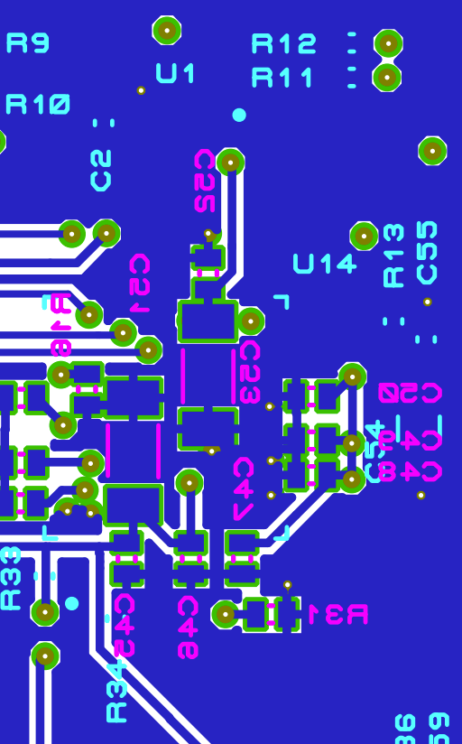
The pcb is 4 layers, the stackup is top layer, ground plane, inner signal layer, bottom layer. The relevant parts of the pcb is shown in these pictures:
top layer


inner signal layer

bottom layer

I have verified the components (values, package size and other data), the footprints against the datasheet, the reference schematic and the wiz550io schematic and pcb.

I have checked the gerber files for errors - none found. I have also had a couple of colleagues double check my work - they couldn’t find any issues either.

I have verified that the pcb is ok - no shorts between 3.3V and ground, between pads or otherwise suspicious measurements.

On the long surviving prototypes I measured the voltages (3.3V in, VDD digital and analog on the W5500) they are stable and within specifications.

Symptoms:
On the W5500 only or W5500 minimal only prototypes the symptoms are that current draw rises quickly to about 130 - 135 mA and sometime after that the W5500 chip dies.

How do I know that the W5500 chip dies? I measure the resistance between 3.3V input and ground on a populated prototype pcb before applying power to it, it is in the kilo-ohm range. after the W5500 has dies, the measurement is just a few hundred ohms. If the W5500 chip is the desoldered, the measurement goes back to kilo-ohm range again.

Obviously something must be wrong with my schematic or pcb layout, but so far we (my colleagues and I) haven’t been able to find it.

Any advice would be great. Thanks.

Below is quick thoughts on the design, not related to the main problem:

  • MMZ1005 is a ferrite bead for signal filtering, select another one for power filtering.
  • In minimal configuration some very important components like EXRES1 resistor are required to keep PHY functioning properly.

Sounds like chip locks up. How fast it happens? Did you have an opportunity to see if it starts heating heavily?

I see you still have SPI connected to the chip. What is going on there? I am not sure but generally some wrong command through SPI may get chip going crazy. Do not know if it is possible, why not!

I can certainly try a test pcb with the EXRES1 resistor fitted, even if I find it unlikely that a missing EXRES1 resistor could make the W5500 die.

The current draw increase happens very quickly, over just a few seconds. We don’t have a thermal camera, but the W5500 chip never feels hot.

SPI - no, there is nothing else connected to the W5500, neither on the SPI nor the other signals on the test pcbs. I just didn’t erase those lines from the schematic - sorry. On a fully populated pcb there is of course a microcontroller connected.

Thanks for the info. How do you solder the chip in the first place? What is the soldering profile?

The prototypes are hand soldered. Soldering iron, microscope and steady hands.

Great, what is the temperature of the soldering iron when soldering?

Let me explain. I killed lots of (let’s say 20 :cry:) W5100 chips hand soldering them at 350C. They did not die completely, but they became unreliable and had strange working artifacts. When I solder chips at iron at 315C, everything is great. In conclusion: high iron temp damages the chip, and this damage may exhibit in very strange ways.

Interesting, I keep the soldering iron at 370 degrees Centigrade (lead free solder you know). I could try preheating the pcb (we have a hot plate, not ideal but it might work) and solder it at a lower temperature.

As a test for the proto try leaded solder at 315C and see how it performs. Or in general: discuss soldering profile which you can find in the datasheet with your process technologist, and decide what you can do. Finally if you have equipment perform reflow as in datasheet for the chip only, all other do hand soldering.

Hand soldered a prototype board using leaded solder at 315C. Unfortunately it didn’t help, the chip still dies. I use a lab power supply with a current limited output, increasing the current limit in steps for the testing. I use the minimal schematic, but added the EXRES1 resistor.
Questions:

  • the external components normally connected to the PHY lines on the chip are not fitted, could that kill the chip?
  • will using a current limited power supply kill the chip?

Sad news, I was hoping it will help.

I do not think so, but can not tell you definitely. For some reason I recall that chip may be also designed for direct transformerless configurations. And probably this question was already asked before, and I do not recall any cautions.

Chip consumes max 140 mA, with latch-up at 200 mA. Given that you have had same behavior with magnetics fitted, problem is not in RX/TX connection.

You said previously that SPI is not connected on minimal circuit, but chip still dies. We are sure that power is not a problem.

Can you please take defective chip, and measure resistance between its 3V3D and 3V3A pints onto ground pins to see where exactly breakdown it?
Also please clarify how /RESET pin is being handled in all scenarios.

And only clock circuit remains. I do not see anything bad about crystal and its properties (50 ppm instead of 30 ppm must not cause this issue?) and rise/fall time of 10 ns. However is it possible for you to attach/solder in somehow classical WIZnet clocking circuit basing on the crystal as a test? One crystal, two caps and one resistor. Another suggestion could be putting current limiting resistor between generator device and XI pin. But this all is searching for black cat in dark room, in opinion more tests are required.

Last, but not least - are all chips from the same batch? Did you purchase them from respective/trustworthy source? I did not see fake chips so far, and hardly believe there will be any, but consider worth checking this aspect.

/RESET pin has internal pullup, no other connection in minimal setup. In full setup, it is connected to the mikrokontroller.
All components are ordered from trustworthy sources (Digikey / Mouser). I have ordered W5500 chips from both, in order to rule out a possible batch problem.

I will measure resistance as soon as I can.
I will look into if we can change the clock circuit.

Just build the circuit on the existing pads in airwire-type wiring. This is a test, no need to make new board. You just need appropriate components. The most tricky is connecting XO, but can be carefully achieved by the thin insulation/lacquer coated copper wire.

Edit: from my experience reset pin needs to be driven low after power up. Your crystal start up time is 10 ms, chip’s reset timing, per datasheet’s 5.5.1, is 1 ms, therefore reset pin must be held low for, let’s say, 20 ms, or better for jumbo period like 0.5 seconds to be sure chip is hard reset properly. No idea if it matters here, just telling how I would do it, and how it works for me (for W5100).